[ENG] 5.2. [DKSF 253.6 IU] How to Use the Module «Logic»?
Rules allow setting a flexible logic scheme of controlling IO lines and relays of a device depending on changing external conditions.
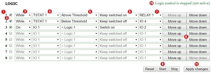
1. Rule Number
The less a line number is, the higher a rule priority is. If two rules form a controversial outgoing command (switch on and switch off an output simultaneously), a rule with a higher priority will work. If rules do not conflict because they control different outputs or form conflict-free commands, then a correlation of their priorities does not influence their work.
Rules of «While» type always have a higher priority in relation to the rules of «If» type, regardless their mutual location in the list.
A rule priority (position in the list) can be changed using buttons 8 («Move up» and «Move down») at the end of a line.
2. Checkbox for Activating a Rule
Rules can be activated by checking corresponding checkboxes. Inactive rules are displayed in gray.
3. Rule Type (Operation Mode of a Rule)
Possible values are: «While», «If». «While» rules respond to changing an input and work constantly. «If» rules respond to the change in an input status.
A «While» rule is designed to program conditions, within which an output is constantly kept in a specified condition when a rule is performed. When a condition is not satisfied, an input status can be changed by other rules.
An «If» rule is designed to program a momentary reaction to a specified event, such as changing a logic level at an IO line or losing a response when Pinger works. Until an input of a rule remains unchanged, an «If» rule does not influence a status of its output, even is a condition of a rule is not satisfied.
«While» rules always have a higher priority, then «If» rules. For example, when one of «While» rules keeps an output switched off, rules of «If» type that switch on an output on the specified event, will not work.
4. Input
Input is an information source for a rule operation. Its possible values are represented in a table:
Value | Description |
|---|---|
RESET | Signal, which is active 5 seconds after starting the module «Logic» or rebooting the module «Logic» by the button «Reset» at the web page. It is used for a primary hardware initiation. For example, it is possible to program a 5-second pulse for a relay at a logic start or issue and IR command to switch a device off. |
IO 1 | IO line 1. Before using it must be switched to the mode «input» at the page «DISCRETE I/O» |
IO 2 | IO line 2. Before using it must be switched to the mode «input» at the page «DISCRETE I/O» |
IO 3 | IO line 3. Before using it must be switched to the mode «input» at the page «DISCRETE I/O» |
IO 4 | IO line 4. Before using it must be switched to the mode «input» at the page «DISCRETE I/O» |
TSTAT 1 | Thermostat 1. A thermostat must be configured at the page «LOGIC» before using |
TSTAT 2 | Thermostat 2. A thermostat must be configured at the page «LOGIC» before using |
PINGER 1 | Pinger 1. A pinger must be configured at the page «LOGIC» before using |
PINGER 2 | Pinger 2. A pinger must be configured at the page «LOGIC» before using |
C.S. ALARM | An alert signal of a smoke sensor (current sensor). The signal «C.S.ALARM» works when parameters of a sensor leave configured conditions «Alert» at the page «SMOKE» of a device web interface |
C.S. FAIL | A signal of smoke sensor (current sensor) failure. The signal «C.S. FAIL» works when parameters of a sensor leave configured conditions «Loop Breakage» and «Loop Short Ciscuit» at the page «SMOKE» if a device web interface |
| C.S. NORM | A signal of a normal operation of a smoke sensor (current sensor). The signal «C.S. NORM» works when parameters of a sensor satisfy configured conditions «Alert», «Loop Breakage», «Loop Short Circuit» at the page «SMOKE» of a device web interface |
| AC PWR | Availability of 220 V power at an input of a device |
5. Condition
A condition within which a rule is applied and a command is issued, which changes a status of an output. An available set of conditions is changed depending on a chosen type of a task. Conditions represent a sense of an input status. Possible values for a pinger are «Silent», «Reponds». For an IO line, possible values are «logic 1», «logic 0». For a thermostat, possible values are «Below Specified Т», «Above Specified Т».
A rule of «If» type works only in the moment of satisfying a condition.
A rule of «While» type works all the time while a condition is satisfied.
6. Command
A command, which is executed when a rule works (a condition is satisfied).
For a rule «If» possible values are – «Switch on», «Switch off», «Switch to». These commands work in the moment when a condition appears.
For a rule «While» possible values are – «Keep switched on», «Keep switched off». These commands work all the time when a condition is satisfied.
7. Output
It is an output, which is controlled by a rule. Its possible values are represented in the table:
Name | Description |
|---|---|
IO 1 | IO line 1. It must be switched to the mode «logic output» at the page «INPUT-OUTPUT» before using |
IO 2 | IO line 2. It must be switched to the mode «logic output» at the page «INPUT-OUTPUT» before using |
IO 3 | IO line 3. It must be switched to the mode «logic output» at the page «INPUT-OUTPUT» before using |
IO 4 | IO line 4. It must be switched to the mode «logic output» at the page «INPUT-OUTPUT» before using |
RELAY 1 | Relay, built into the body of a device. It must be switched to the mode «Logic» at the page «220 V MANAGEMENT» before using |
| RELAY 2 | Relay, built into the body of a device. It must be switched to the mode «Logic» at the page «220 V MANAGEMENT» before using |
SNMP 1 | SNMP Setter 1. It must be configured at the page «LOGIC» before using |
SNMP 2 | SNMP Setter 2. It must be configured at the page «LOGIC» before using |
| SNMP 3 | SNMP Setter 3. It must be configured at the page «LOGIC» before using |
| SNMP 4 | SNMP Setter 4. It must be configured at the page «LOGIC» before using |
IR 1 | IR command 1. A command must be recorded and saved into the cell 1 at the page «IR COMMANDS» before using |
IR 2 | IR command 2. A command must be recorded and saved into the cell 2 at the page «IR COMMANDS» before using |
IR 3 | IR command 3. A command must be recorded and saved into the cell 3 at the page «IR COMMANDS» before using |
IR 4 | IR command 4. A command must be recorded and saved into the cell 4 at the page «IR COMMANDS» before using |
C.S. PWR | Before using the C.S. PWR output, there is a need to switch a loop power supply into the mode «Controlled by Logic» at the page «SMOKE» |
8. Buttons Move Up/Move Down
The buttons are designed to change the position of a rule in the list and thus to change a priority of the rule. If rules form conflicting commands for an output, a rule that is higher in the list will work. However, «While» rules always have a higher priority relative to «If» rules, regardless their mutual location in the list.
9. Controls
Controls work immediately after clicking. There is no need to click the button «Apply changes» additionally.
Buttons «Start» and «Stop» control starting and stopping of rules operation. This state is kept when a device is switched off. If rules are stopped, a warning line of a logic status «10» appears.
A button «Reset» switches the outputs, which are controlled by a logic module, into a specified initial status and initiates a reset signal. Rules, which have a reset signal RESET as an input, can switch the outputs into a necessary required initial status. There is a need to note that if rules are not stopped before clicking the button «Reset», a status of outputs can be immediately changed and a reset command will not have any external effect.
10. Status Line
If a rule operation is stopped, a warning line appears.
11. Button for Saving Changes
After configuring all necessary settings, click the button «Apply changes».
Restrictions
A logic module of a NetPing IO v2 device does not support the next «inputs» of a rule:
- TSTAT1;
- TSTAT2;
- C.S. ALARM;
- C.S. FAIL;
- C.S. NORM;
- AC PWR
A logic module of a NetPing IO v2 device does not support the next «outputs» of a rule:
- RELAY1;
- RELAY2;
- IR1;
- IR2;
- IR3;
- IR4;
- C.S. PWR