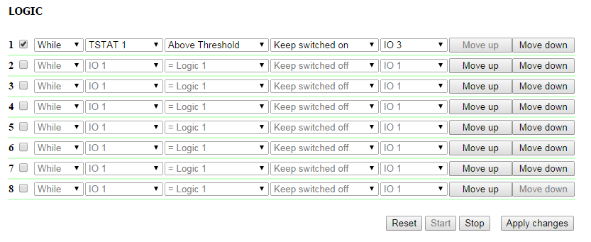
[DKSF 70.3] Page LOGIC web interface
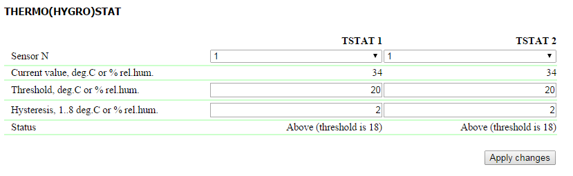
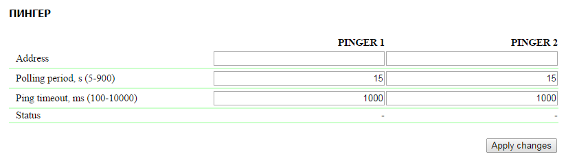
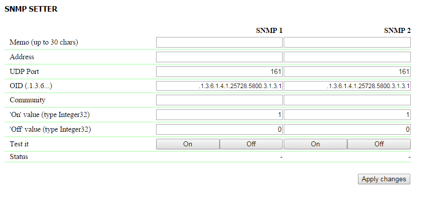
A logic module of DKSF 70.2 IU firmware is designed with the aim of a simple automation and can perform such tasks like maintaining a microclimate, managing an automated turning on/off a backup equipment, etc. Logic works on a basis of the rules, programmed by a user through a web interface. This page describes a module operation algorithm and its configuring possibilities. Rules allow to set a flexible logic scheme of managing IO lines and relays of a device depending on varying external conditions. Every position of a rule line is described below. 1. A rule number. The less is a line number, the higher is a rule priority. If two rules form a conflicting output command (turn on and turn off an output simulteneously), a rule with a higher priority will work. If rules do not conflict – e.g. they manage different outputs or form conflict-free commands – then correlation of their priorities does not matter; 2. A Checkbox for turning on a rule. A rule can be deactivated by unchecking a checkbox. Inactive rules are displayed in grey; 3. A rule type. Possible values are: «While», «If». «While» rules react on an input status immediately and run constantly. «If» rules react on changing an input status (the second position in a rule line). «While» rule is designed to program conditions under which an output is constantly kept in a specified status, until a condition works. When a condition is not fulfilled, an output status can be changed by other rules. «If» rule is designed to program a short-term reaction to a specified event, such as changing a logic level of an IO line and losing a response when a Pinger works. Until an input of a rule remains unchanged, a rule «If» does not influence status of its output even if a condition of a rule is fulfilled. «While» rules always have a higher priority than «If» rules. For example, when one of the «While» rules keeps an output in a status turned off, rules of «If» type that include an output on a specified event, will not work; 4. Input. An input is a source of information for a rule operation. Its possible values are represented in a table below: Denotation Explanation RESET A RESET input is described in the section "A reset and an initial status of outputs” IO1 IO line 1. It should be set to an input mode on the page Input-Output before using. IO2 IO line 2. It should be set to an input mode on the page Input-Output before using. IO3 IO line 3. It should be set to an input mode on the page Input-Output before using. IO4 IO line 4. It should be set to an input mode on the page Input-Output before using. TSTAT1 Thermostat 1. A thermostat must be properly configured on the page "Logic" before using. TSTAT2 Термостат 2. A thermostat must be properly configured on the page "Logic" before using. PINGER1 Pinger 1. A pinger must be configured on the page "Logic" before using. PINGER2 Pinger 2. A pinger must be configured on the page "Logic" before using. C.S. ALARM In case of using values C.S.ALARM, C.S.FAIL a current sensor should be configured. Depending on a type of a chosen input, a set of conditions for the rule is changed. C.S. FAIL In case of using values C.S.ALARM, C.S.FAIL a current sensor should be configured. Depending on a type of a chosen input, a set of conditions for the rule is changed. 5. Condition is a condition, within which a rule is applied and a command that changes an output status is issued. An available set of conditions is changed depending on a chosen type of Input and reflects a sense of an input status. For a Pinger possible values are “Silent”, “Responds”. For an IO line possible values are “logic 1”, “logic 0”. For a Thermostat possible values are “Below a specified Т”,”Above a specified Т”. An «If» type rule work only in the moment of fulfilling a condition. A «While» type rule performs all the time while a condition is fulfilled. 6. Command is a command that is issued when a rule is performed (a condition is fulfilled). For an «If» rule possible values are «Turn on», «Turn off». These commands perform in the moment of fulfilling a condition. For a «While» rule possible values are «Keep Turned On», «Keep Turned Off». These commands perform all the time while a condition is fulfilled. 7. Output is an output that is managed by a rule. Possible values are: IO1, IO2, IO3, IO4 , RELAY 1, IR 1, IR 2, IR 3, IR 4(one of the first 4 IR commands), CS PWR. Denotation Explanation IO1 IO line 1. It should be set to a logic output mode on the page Input-Output before using. IO2 IO line 2. It should be set to a logic output mode on the page Input-Output before using. IO3 IO line 3. It should be set to a logic output mode on the page Input-Output before using. IO4 IO line 4. It should be set to a logic output mode on the page Input-Output before using. RELAY1 A relay built into a body of a device. Before using a relay, it should be switched to a logic output mode on the page Relay Management. SNMP1 SNMP Setter 1. It should be configured on the page "Logic" before using. SNMP2 SNMP Setter 2. It should be configured on the page "Logic" before using. IR1 IR command 1. A command should be recorded and saved into a cell 1 before using. IR2 IR command 2. A command should be recorded and saved into a cell 2 before using. IR3 IR command 3. A command should be recorded and saved into a cell 3 before using. IR4 IR command 4. A command should be recorded and saved into a cell 4 before using. C.S. PWR Before using a C.S. PWR output there is a need to switch a Loop Power Supply in a mode Managed by Logic on the page Current Sensor. After setting all necessary changes, press the button «Apply changes». A thermostat is used to maintain a temperature. Besides a programmed thermostat, there is a need to set minimum two rules: one rule for turning on a heater or a cooler and another one for turning it off. It is possible to configure no more than two thermostat channels – TSTAT1, TSTAT2. A corresponding thermostat is chosen as a source of information (input) in rules that manage a heater or a cooler. The fields “Current temperature, degrees C” and “Status” are used to view a sensor status and its readings. Configuration parameters and a thermostat status are described below. Sensor N – a number of a temperature sensor, with which a thermostat works. Up to 8 temperature sensors are plugged to a device with individual number from 1 to 8. On default: 1 A specified temperature - A temperature, which will be maintained by a thermostat (in whole degrees of Celsius, a value can be negative) On default: 20. Hysteresis - Hysteresis sets a "corridor" close to a specified temperature, in limits of which a thermostat does not react to temperature fluctuations. This function allows to avoid occasional frequent switching of a heater (cooler) caused by natural spontaneous fluctuations measured by a temperature sensor. If a current thermostat status is «temperature above a specified one», then a threshold of a status switching is a specified temperature minus a hysteresis value. And vice versa, if a current status is "temperature below a specified one", then a threshold is a specified temperature plus a hysteresis value. As soon as reducing or increasing temperature reaches the value of a threshold (taking into account a hysteresis) and thereby leaves the limits of a corridor, a thermostat status is changed to an opposite one. On default: 2 After setting all necessary changes, press the button «Apply changes». Pinger checks an availability of a specified address via network. A result of a test (a pinger status) can be selected as an «input» of a rule. It is possible to configure no more than two pingers – PINGER1, PINGER2. A typical use of a pinger is an automatic turning on a power supply of backup equipment if a connection line fails. Parameters of a configuration and a pinger status are described below. Requested address – is an address of a device, which is being checked for its availability. 0.0.0.0 disables requesting. On default: 0.0.0.0 Polling period, s (5-900) - is a period of repeating ping tests in seconds. A value is chosen depending on a necessary speed of discovering a failure and on the other hand a limit of a service traffic in a network. Also there is a need to take into account that too frequent power supply switching can decrease a wearout time of equipment. If there is no response, a ping is repeated after timeout is over, not when the next polling period starts. On default: 15 One ping timeout, ms (100-10000) - is time for ping to wait for a response. Timeout is chosen depending on a speed of a local network as well as a frequency of repeating pings that are not responded. If there is no response to ping after a specified timeout is over, ping sending is immediately stopped. If there is still no response after 5 repeated sending, a pinger status is changed to «does not respond», and repeats are stopped until the next polling period starts. On default: 1000 Status – possible values «Responds», «Silent». If requesting is not completed, a status can be undefined. In this case the rules depending on a pinger status, do not form any commands, and their outputs are managed by other rules or keep a previous condition. Pinger status is updated automatically nearly 4 times a minute. After setting up all values there is a need to click the button «Apply changes». SNMP Setter is used as a rule output and is designed to specify an SNMP OID variable in a remote device via an SNMP v1 protocol. In particular, it is possible to manage IO lines and a relay of another NetPing device via a network. If there is no response about a request fulfilling, a device will try its attempt twice. A channel number (SNMP 1, SNMP 2) - this number is specified as a rule output. Memo - A custom text up to 30 characters. On default: empty IP address – is an IP address, to which will be sent an SNMP SET command. On default: 0.0.0.0 Port - is a port, which listens an SNMP agent on a remote device. On default: 161 OID - is an identificator of a variable, which will be set on a remote device. It is necessary to indicate a compete OID in numeric notation, starting from .1.3… A list of variables is in a MIB file of a device (in a specific format) or in a documentation of a device. To view a MIB file conveniently as a tree and to check functions of variables, it is possible to use a freely distributed program iReasoning MIB Browser or a similar one. On default: .1.3.6.1.4.1.25728.5800.3.1.3.1 Сommunity - Snmp Community configured on a remote device. On default: пусто On Value – is a value, which will be recorded into OID on a remote device when invoking an action “Turn on” or clicking the button On, or by quitting logic. Value type is 32-bit signed integer. On default: 1 Off Value – is a value, which will be recorded into OID on a remote device when invoking an action “Turn off” or clicking the button Off, or by quitting logic. Value type is 32-bit signed integer. On default: 0 Test - when clicking the buttons “On”and “Off”, a device immediately sends corresponding requests with values «on» or «off». Status - several seconds after sending a request to set a variable into a Status field, a result is displayed. «ОК» means that a confirmation is received, and a variable is set successfully. «Timeout» means that a confirmation is not received. It can be a result of an unavailability of controllable device as well as its failure, wrong ip address, port or community. Other variants mean that a response with an error code was received, and its textual explanation is represented in a status line. After changing the settings click the button «Apply changes». After firmware starts working or a Reset button is clicked on a web-page of Logic, outputs, managed by Logic, are switched to the determined initial status. On default, it is a status «off», or logic 0. Another status can be specified using the rule, utilizing the input reset signal RESET. 5s after a reset, a signal has a value logic 1. A rule with a condition «= 1» operates in the moment of reset. A rule with a condition «= 0» works 5s after a reset moment. Therefore it is possible to form a 5-second external reset impulse on one or several outputs or provide a correct sequence of power supply to external devices. If a logic operation is stopped, then rules «If/While RESET = 0», corresponding to the completing of the RESET signal, will work after clicking the control button «Start» on the Logic web page.List of Rules
Thermostat
Pinger
SNMP Setter
Reset and Initial Statuses of Outputs