[ENG] [DKST 51] Connection, Installion, and Initial Configuration of the Device
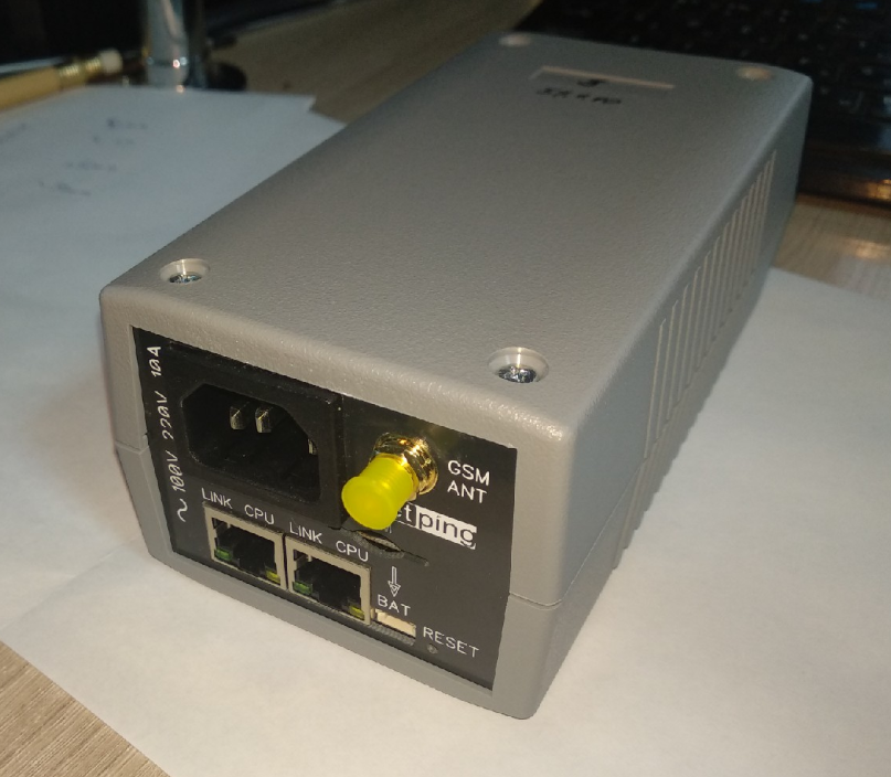
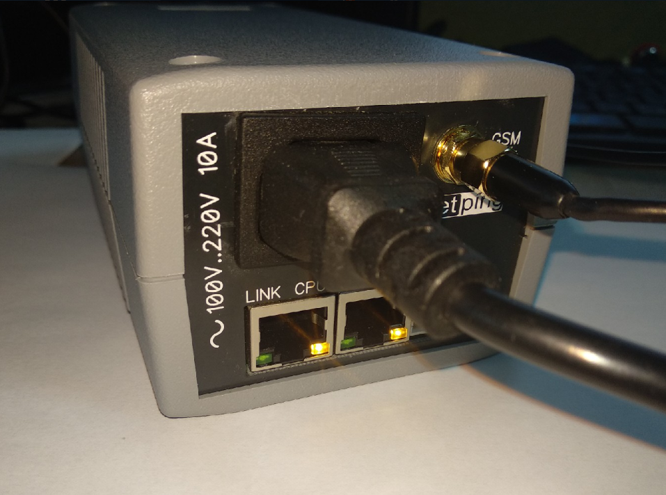
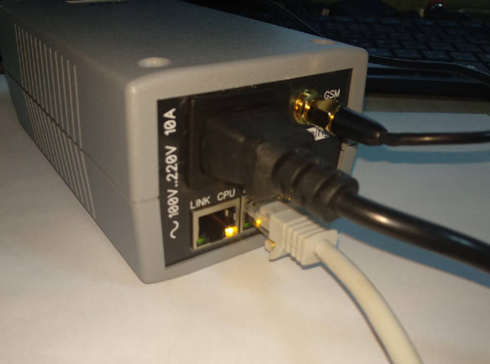
The page shows the photos of the device NetPing 2 IP PDU GSM3G 203R15 in the text.
Step 1
Unpack the device and install it on a horizontal surface.
Step 2
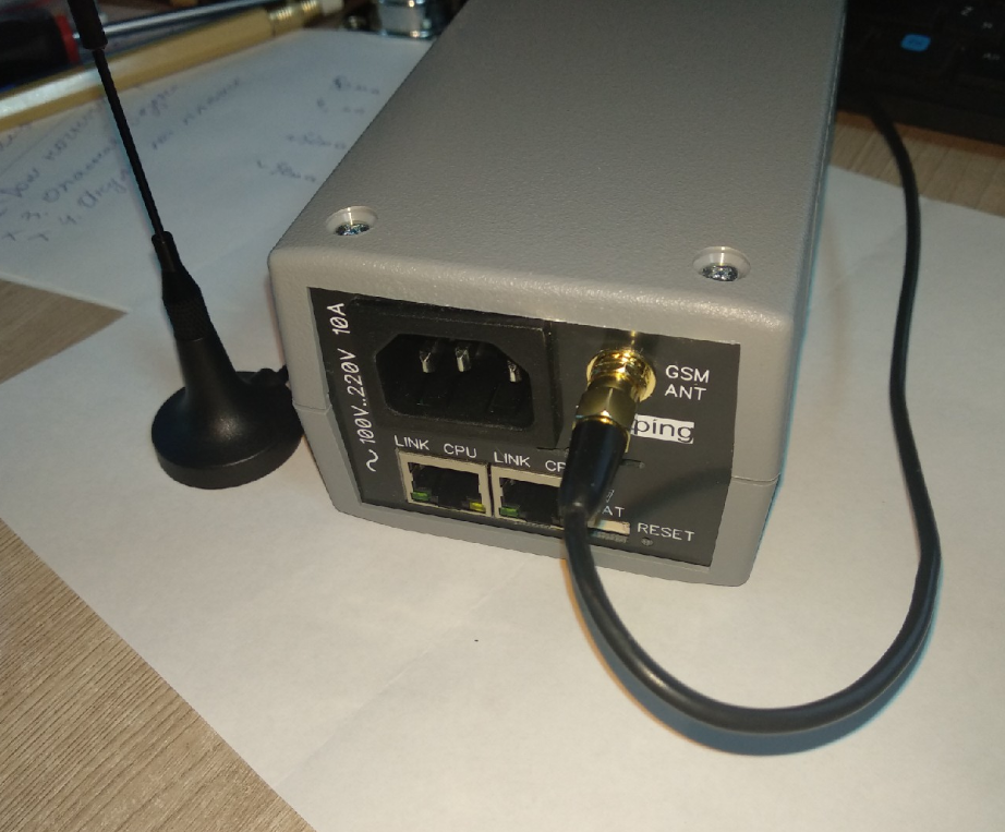
For the model NetPing 2 IP PDU GSM3G 203R15, with a built-in GSM modem.
Plug a GSM antenna to the device and locate it in the area of the strong signal of a cell operator. The signal strength can be controlled using a cell phone according to the number of segments of the signal indicator on the display.
Step 3
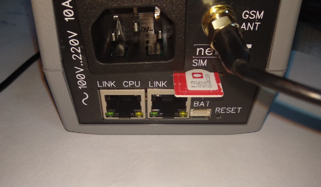
For the model NetPing 2 IP PDU GSM3G 203R15 , with a built-in GSM modem
Insert a SIM card in a corresponding slot at the front panel of a device until you can hear a click. Pay attention to turning a SIM card contacts down and a cut-off corner into a device.
A SIM card should be inserted only in the device that is powered off.
Step 4
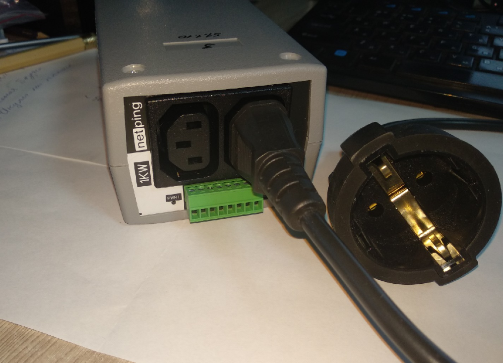
Connect the equipment (the load) the power of which should be controlled, to the «PWR» sockets at the back panel of a device. Power cords or adapters for connecting devices are not included in the shipping kit.
Connect external sensors or running devices to the IO lines of a device (see the details in the section «Connecting, Installing, and Initial Configuration of a Device»).
External sensors and load should be connected only when a device is powered off.
Important! It is not recommended to connect the real network and computer equipment to the device at once at the first switching on and getting acquainted with the operation logic of the device. Frequent cycles of switching on/off can cause the failure of the equipment. For the time of getting acquainted with the device, it is possible to plug any indifferent load to the power sockets (for example, a table lamp) or track a power status at power sockets watching the glowing of the corresponding LEDs.
Step 5
Plug the device to the power grid.
Important! A device is designed for plugging to the power grid of the voltage 100 V - 250 V and the frequency of 50/60 Hz. Do not plug a device to the power grids with other parameters!
The power indicator is glowing of the CPU LEDs at Ethernet ports at the front panel of a device. In the process of the device initialization, LEDs blink several times, which shows switching on a device, and after this, they will be glowing constantly.
Step 6
Connect a device to the local network or the computer.
Glowing of the Link LED at the corresponding Ethernet port at the front panel of a device will mean that the physical connection is successfully established.
The second Ethernet port can be used for connecting any Ethernet-devices, including other NetPing devices, «in a chain».
The device is connected and ready or the operation.
The device that has been just purchased or the device with parameters that have been reset to default values requires the initial configuration of network addresses and parameters for controlling the loads. After this, a device can be installed in the existing network. It can be configured further by using remote access to a device. More information on the configuration see in the document «Firmware Description». Where can I get a document with the firmware description?
