[ENG] [DKST 51] Connecting External Sensors and Accessories
You can find the information about configuration of the device and receiving notifications from sensors in the document: «User Guide».
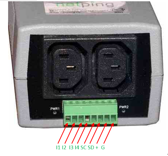
The description of contacts
In order to connect sensors to the device conveniently, use the terminal block. Use a slotted screwdriver with a slot width of 2.5 mm to secure the wires in the terminal block. The pinout of the contacts on the terminal block is as follows:
| Contact | Description |
|---|---|
| I1-I4 | IO-line 1–4 |
| SC | I2C digital bus contacts, synchronization line |
| SD | i2C digital bus contacts, data line |
| + | Supply voltage +5 V |
| G | Groundbed (common) |
i2C Connecting sensors and devices to the i2C bus
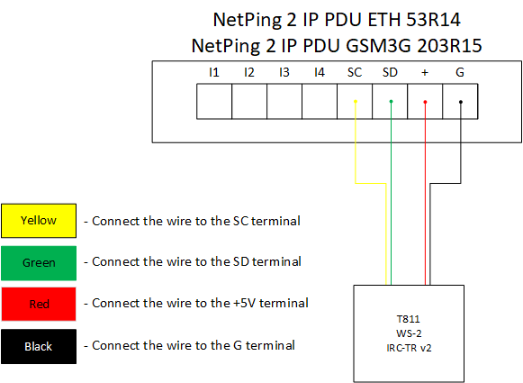
Devices and sensors are connected via a 4-wire circuit. The color of the loop wires is identical for all sensors and devices manufactured by NetPing east Co Ltd.
Only sensors and devices of own design are supported, these include:
- Temperature sensor T811 — up to 8 pc.;
- Humidity sensor WS-2 — 1 pc.;
- NetPing IRC-TR v2 — 1 pc.;
All sensors and devices are connected in parallel to each other in the same terminal blocks according to the following scheme:
| Sensor / Device Loop | Device terminal |
|---|---|
Yellow | SC |
Green | SD |
Red | + |
Black | G |
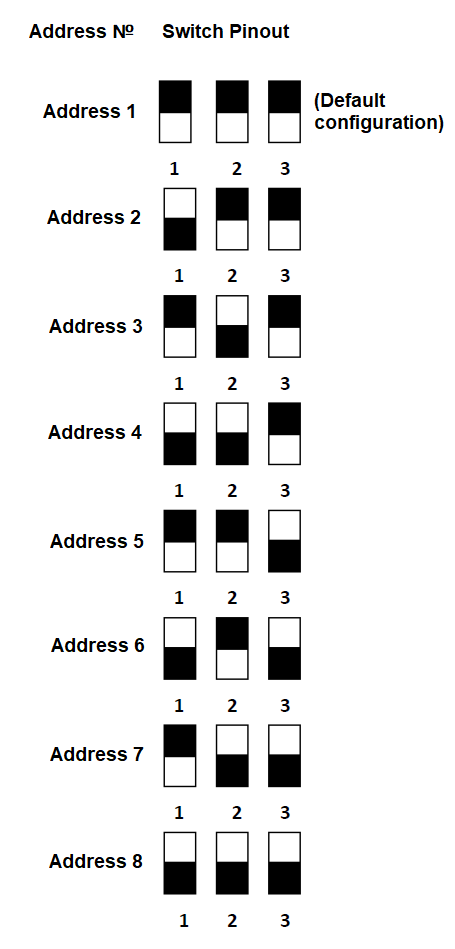
Important! It is prohibited to connect temperature sensors with the same numbers (ID) to the device.
Set each temperature sensor with its own number using the switches on the sensor board. To set the switches, remove the top cover of the sensor
Depending on the ID, the temperature sensor will be displayed on the corresponding channel in the device’s web interface.
Sensors of the "Dry contact" type
Attention! There are 12 V, up to 200 mA on the input / output lines of the device (IO1-IO4) in the “output” mode, . If used improperly, the connected equipment may fail.
The number of connected dry contact sensors is limited by free IO lines of the device and the total current consumption of the sensors, if they require additional power.
If the sensor needs extra +12 V power, you need to use one of the input / output lines in the "output" mode. Thus, it is possible to control the power of the sensor additionally using a logical level on the line. This can be useful, for example, in the case of sensors whose alarm is reset by removing power.
The corresponding IO line to which the signal wire from the sensor is connected must be switched to the “input” mode in the device settings.
Two wire sensors
Sensors and other signal sources which do not require additional power or they are powered from other power sources and it is isolated from the signal line, connected to the IO and GND terminals of the device. The polarity of the connection is important unless otherwise directly indicated in the documentation for the sensor.
Such type of sensors include:
- Supply voltage sensor
- NetPing Supply Voltage Sensor 995S2 (N.Z. and N.O. contacts (3 wires in total) - see the sensor documentation for details);
- Door sensor metal
- Air Flow Sensor (model AMC520)
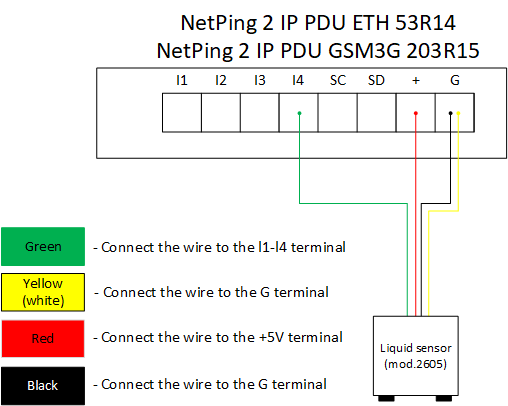
Liquid sensor (mod.2605)
Sensor Loop | Device Terminal |
|---|---|
Green | I1-I4 |
Yellow | G |
Brown | + |
White | G |
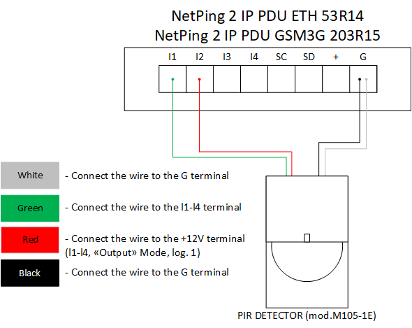
PIR DETECTOR (mod.M105-1E)
| Sensor Loop (coloured) | Sensor Loop (flat) | Device Terminal |
|---|---|---|
| Green | Marked (red) wire | I1-I4 |
| White | The first wire after the marked one | GND |
| Black | The second wire after the marked one | GND |
| Red | The third wire after the marked one | +12 V (I1-I4 on the mode «output», log. 1) |
Actuation Devices
Attention! There are 12 V, up to 200 mA on the input / output lines of the device (IO1-IO4) in the “output” mode, . If used improperly, the connected equipment may fail.
The number of actuation devices is limited by free IO lines of the device and the total current consumption of devices in active mode.
If the device requires +12 V power, one of the I / O lines in the “output” mode is used.
The corresponding IO line to which the signal wire from the sensor is connected must be switched to the “input” mode in the device settings.
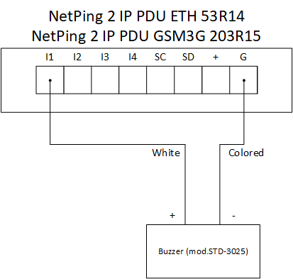
Buzzer (mod.STD-3025)
| Buzzer wire | Device terminal |
|---|---|
| White | +12 В (I1-I4 in the mode «output», log. 1) |
| Coloured | GND |
The logic level on the line in the “output” mode which is used for power will control the operation of the buzzer. When the log.1 - the buzzer is active, with the log. 0 - the buzzer is off.
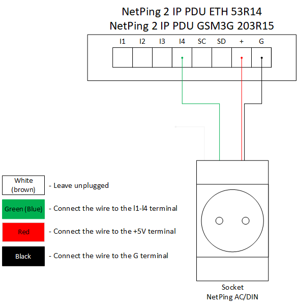
NetPing AC/DIN socket
| Socket Loop | Device terminal |
|---|---|
| Red | +5 В |
| Black | GND |
Blue (green) | I1-I4 |
| Brown (white) | - |
NetPing AC/DIN socket uses a relay with normally closed contacts to switch the load. This means that if the control wire is not connected anywhere, 220 V will be present on the socket and the load will be turned on.
In the "log.0” condition, 220 V will be present on the IO control line at the output of the socket, the load will be turned on. In the "log.1” condition the socket will be de-energized, the load will be off.
Important! The brown (white) wire is not used and should not be connected!
