[ENG] [2PWR,v2SMS] Plugging External Sensors
Configuring a device and receiving notifications from sensors can be seen in the document «Firmware description».
Description of Contacts
To make plugging of sensors to a device convenient, a terminal block is used. To fix wires in a terminal block, use a slotted screwdriver with a slot width of 2,5 mm. Pinout of contacts on a terminal block looks like the next:
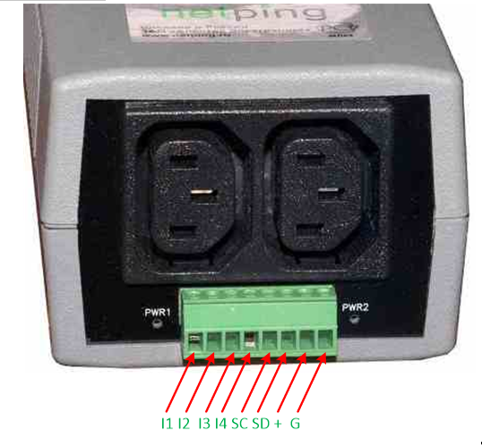
| Contact | Description |
|---|---|
| I1-I4 | IO line 1-4 |
| SC | Contacts of a digital bus i2C, synchronization line |
| SD | Contacts of a digital bus i2C, data line |
| + | Power voltage +5V |
| G | Ground (common) |
Plugging temperature sensors T811
Eight temperature sensors are plugged in parallel one to another in the same terminals.
Colored Loop | Contact Name |
|---|---|
Yellow | SC |
Green | SD |
Red | + |
Black | G |
Important! It is prohibited to plug temperature sensors with the same identification numbers (ID) to a device.
Set an ID for every temperature sensor using switches on a board of a sensor. To set switches, take off an upper lid of a sensor.
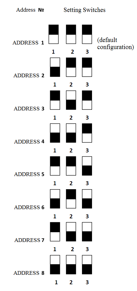
Depending on ID, a temperature sensor will be displayed on a corresponding channel in a web interface of a device.
Plugging Temperature Sensors TS/WT
All 8 temperature sensors are plugged in parallel one to another.
Flat Loop | Contact Name |
|---|---|
Labeled (red) wire | SC |
The first wire after a labeled one | SD |
The second wire after a labeled one | + |
The third wire after a labeled one | G |
Important! it is prohibited to plug temperature sensors with the same identification numbers (ID) to a device.
Depending on ID, a temperature sensor will be displayed on a corresponding channel in a web interface of a device.
Plugging a humidity sensor WS-2
A loop of a sensor is a flat loop with a labeled first wire (red).
| Colored Loop | Flat Loop | Contact Name |
|---|---|---|
| Yellow | Labeled (red) wire | SC |
| Green | The first wire after a labeled one | SD |
| Red | The second wire after a labeled one | + |
| Black | The third wire after a labeled one | G |
Plugging IR Module IRC-TR v2
| Colored Loop | Flat Loop | Contact Name |
|---|---|---|
| Yellow | Labeled (red) wire | SC |
| Green | The first wire after a labeled one | SD |
| Red | The second wire after a labeled one | + |
| Black | The third wire after a labeled one | G |
Plugging a Supply Voltage Sensor
A sensor is a «dry contact», therefore the order of connecting wires is irrelevant. The number of plugged sensors is limited only by a number of free IO lines.
Loop | Contact Name |
|---|---|
First wire | I1-I4 |
Second wire | G |
The order of connecting wires is irrelevant. Depending on the output (I1-I4) on a terminal block, where a sensor is plugged in, it is displayed on the same channel IO1-IO4 in a web interface of a device.
IO lines, to which sensors are plugged must be configured as the «input» in an interface of a device!
Plugging a door sensor
A sensor is a «dry contact», therefore the order of connecting wires is irrelevant. The number of plugged sensors is limited only by a number of free IO lines.
Loop | Contact Name |
|---|---|
First wire | I1-I4 |
Second wire | G |
Depending on the output (I1-I4) on a terminal block, where a sensor is plugged in, it is displayed on the same channel IO1-IO4 in a web interface of a device.
IO lines, to which sensors are connected, must be configured as the «input» in an interface of a device!
Plugging a leakage sensor
The number of plugged sensors is limited only by a number of free IO lines.
Colored Loop | Contact Name |
|---|---|
Green | I1-I4 |
Yellow (white) | G |
Red | + |
Black | G |
Depending on the output (I1-I4) on a terminal block, where a sensor is plugged in, it is displayed on the same channel IO1-IO4 in a web interface of a device.
IO lines, to which sensors are connected, must be configured as the «input» in an interface of a device!
Plugging NetPing AC/DIN sockets
The number of plugged NetPing AC/DIN sockets is limited only by a number of free IO lines.
When connecting a socket to a device, all wires are used, except a brown (white) one. An IO line, to which a NetPing AC/DIN socket is connected, needs to be switched into the «output» status. When a status is «logic 0», 220V will be present on an IO line, and a load will be switched on. When a status is «logic 1» on an IO line, a socket will be de-energized, a load switched off.
Important! A brown (white) wire is not used and must stay unplugged!
Loop | Contact Name |
|---|---|
Red | + |
Black | G |
Blue (green) | I1-I4 |
To commute a load in NetPing AC/DIN, a relay with normally closed contacts is used. This means that if a control wire is unplugged, 220 V will be present in a socket, and a load will be switched on.