[ENG] 5.7. [DKSF 253.6 IU] Examples of Setting the Module «Logic»
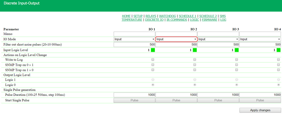
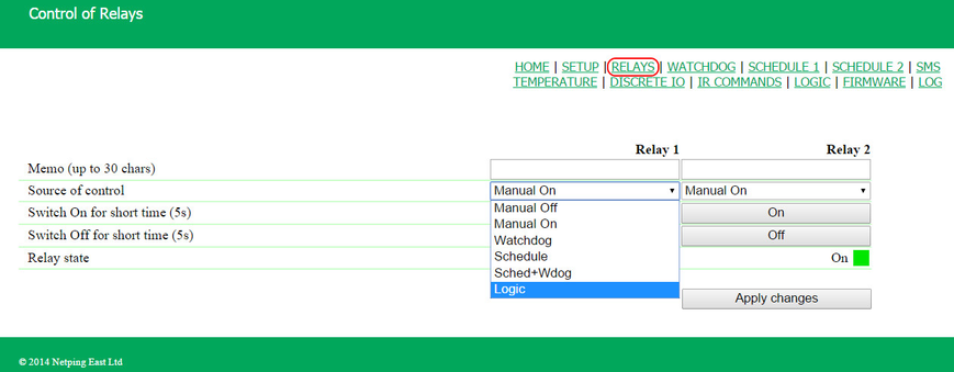
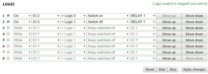
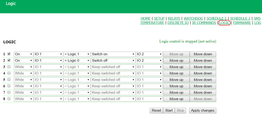
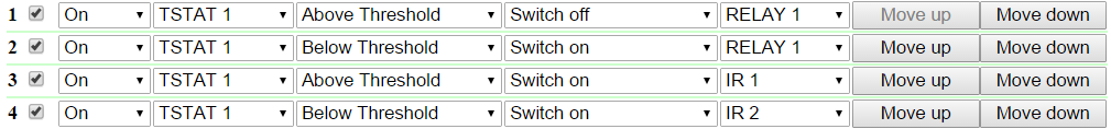
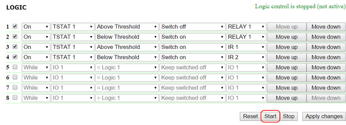
At this page, several simplest examples of configuring the module «Logic» are represented. It goes without saying, necessary sensors, as well as external management modules, are already connected to NetPing devices and NetPing devices are previously configured for performing their specific tasks. A NetPing device with a connected external temperature sensor allows to implement functions of a thermostat, supporting a specified range of temperatures by turning on/off a device for heating and/or cooling in the automatic mode. Task: It is necessary to maintain a temperature of 20°C indoors. Solution: Let us suppose that an electric heater, which warms a certain room, is connected to a controllable socket №1 of a NetPing device. There is an air conditioner in the room, which is managed by an external IR management module IRC-TR v2. For automation of controlling a heater and an air conditioner to maintain a necessary temperature, there is a need to go to the page «LOGIC» of a device web interface: There is a need to check checkboxes for first four rules and configure the next settings: These rules mean that if a temperature in a thermostat 1 (TSTAT1) will exceed a specified one (i.e. above 20°C), an electric heater will be turned off automatically (RELAY 1) and an air conditioner will be turned on the same automatically (IR 1) (rules №1 and №3). To avoid frequent turning on/turning off a heater and an air conditioner, there is a switching hysteresis in a thermostat, which will be described below. If a temperature will fall below a specified value, an air conditioner will be turned off (IR 2) and a heater will be turned on (RELAY 1) (rules №2 and №4). After setting up the rules, there is a need to click the button «Apply changes». The next step is a configuration of the module «THERMO(HYDRO)STAT», on the basis of which previously configured rules will work: A temperature sensor №3 is used to measure a temperature indoors. In the module «THERMO(HYDRO)STAT» there is a need to configure TSTAT1 by choosing a sensor №3 from a drop-down list. Then specify a threshold of 20°C and a switching hysteresis of 2°C. A hysteresis sets a «corridor» around a specified temperature, within which a thermostat does not respond to temperature fluctuations. This function allows to avoid frequent random switching of a heater (a cooler) caused by natural spontaneous fluctuations of a temperature measured by a temperature sensor. If a current status of a thermostat is «above», then a threshold for switching a status is a specified temperature minus a hysteresis value. And vice versa, if a current status is «below», then a threshold for switching is a specified temperature plus a hysteresis value. As soon as a temperature falls or rises and reaches a threshold value including hysteresis thus leaving the limits of «corridor», a status of a thermostat is changed to the opposite one. After configuring a thermostat, there is a need to click the button «Apply changes». Recording, saving and replaying IR commands to control an air conditioner is indicated in the corresponding section of a user guide (works for devices supporting an IR control module IRC-TR v2). Except indicating a relay as an «output» of a rule, there is a need to indicate that this relay will be used together with a logic module. To do this, there is a need to go to the page «220V MANAGEMENT» of a device web interface and choose a management mode «Logic»: After changing a management mode, there is a need to click the button «Apply changes». The last step of configuration is starting logic on a corresponding page of a web interface by clicking the button «Start»: A NetPing device, to which shock sensor PI-90D and siren alarm АС-10 are connected, can perform security functions for remote objects and closets with equipment. Task: Organising a warning alarm for a remote control of a security guard when breaking a wiring closet with equipment. Solution: Let us suppose that shock sensor PI-90D, which is installed into a closet with equipment, is connected to the IO line №2 of a NetPing device, while siren alarm АС-10, which is displayed at a remote control of a security guard, is connected to the Relay 1. To configure NetPing for security measures, there is a need to set the next rules in the module «Logic»: These rules mean when the shock sensor PI-90D (IO 2) triggers, then a warning alarm АС-10 (RELAY 1) will be activated (rule №1) until a level of an IO line №2 has got a value «logic 1» (rule №2). After setting up rules, there is a need to click the button «Apply changes». The next step is a necessity to configure an operation mode of an IO line at the page «INPUT-OUTPUT» of a device web interface. An IO line must work in the mode «input»: Besides indicating a relay as an «output» for a rule, there is a need to specify that this relay will be used together with a logic module. To do this, there is a need to go to the page «220V MANAGEMENT» of a device web interface and choose a relay management mode «Logic»: After choosing a source of control for a relay, there is a need to click the button «Apply changes». The last step of configuration is starting logic at the corresponding page of a web interface by clicking the button «Start»: Configuring a Thermostat
.png?version=1&modificationDate=1435572115786&cacheVersion=1&api=v2&width=923&height=250)

Example of Warning Alarm When a Shock Sensor Triggered