[ENG] [2PWR,v2SMS] Connecting, Installing, and Initial Configuration of a Device
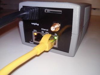
The page has photos of a NetPing 2/PWR-220 v2/SMS device in the text.
To prepare a device for operation, do the next: | |
1. Take a device out of the box and install on a horizontal surface.
|
|
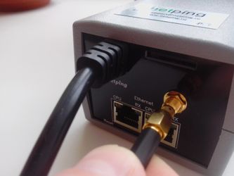
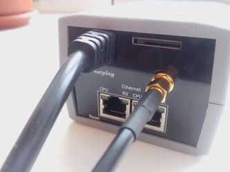
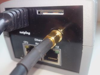
2. Plug a GSM antenna to a device and locate it in the place of a reliable reception of the cell operator's signal (for a NetPing 2/PWR-220 v2/SMS device with a built-in GSM modem). The availability of a signal can be controlled using a cell phone according to the number of segments in the power indicator on a display of the phone. |
|
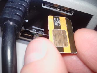
3. Insert a SIM card until the click in a corresponding jack on a front panel of a device (for a NetPing 2/PWR-220 v2/SMS device with a built-n GSM modem). Please, pay attention so that a SIM card is turned contacts up. A SIM-card must be installed only in a de-energized NetPing 2/PWR-220 v2/SMS device. |
|
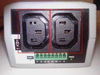
4. Plug the equipment, power of which must be controlled, to «PWR» sockets on a back panel of a device. To make a connection convenient, use the «monitor – system unit» cords or an adapter to connect PWR-220. Cords and adapters are not included into a shipping kit and can be purchased separately if necessary. |
|
5. Plug external sensors to a device (see the details in the section «Plugging External Sensors») and/or a load. External sensors and/or load can be plugged only to a de-energized device. | |
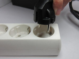
6. Plug a device to a power supply network. |
|
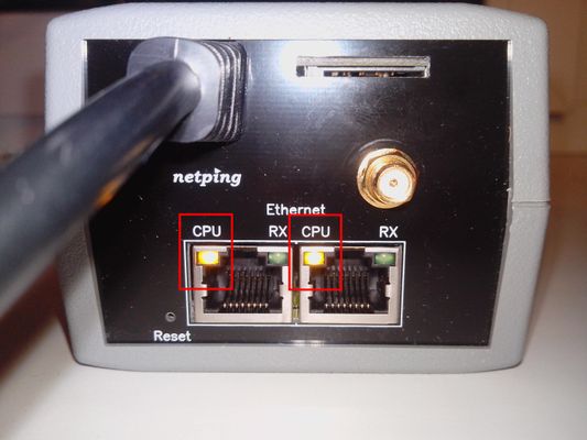
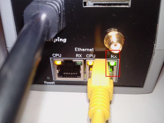
Glowing of CPU LEDs near Ethernet ports on a front panel of a device will be an indicator of power supply.
In the process of a device initialiation, LEDs blink several times indicating switching on of a device, and then will be glowing constantly. | |
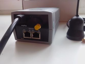
7. Connect a device to the office Ethernet network to any free Ethernet port of a switch. |
|
Glowing of a link LED near a corresponding Ethernet port on a front panel of a device will mean that a connection is successfully established.
The second Ethernet port may be used to plug any Ethernet devices including other NetPing devices, in a «chain». | |
A device is connected and ready to work. A device that has been purchased right now or a device for which a procedure of resetting parameters to default values has been performed (see «Resetting Parameters to Default Values»), requires the initial configuration of network addresses and parameters of load control. After this, a device can be installed into an existing network. Its further configuration may be performed by using a remote access to a device. More detailed information about a configuration can be found in the document «Firmware description». Where to Get a Document with a Firmware Description? Important! It is not recommended to connect real network and computer equipment to power sockets at the first switching on and familiarizing with the operation logic of a device. Frequent cycles of switching on/off may cause equipment failure. During the time of familiarizing with a device, it is possible to conect an indifferent load (for example, a table lamp) to power sockets or track a power supply status on power sockets by glowing of corresponding LEDs. | |