[ENG] [DKST 51] Features of Local Controls, LEDs, and Sockets on a Case of the Device
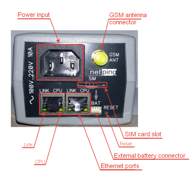
Front View
| Element | Description |
|---|---|
| Power Input | A socket for connecting the device to the power grid. 100..250В 50/60 Hz |
| GSM antenna connector | A socket for connecting an external GSM antenna. SMA with a connector. It is included only in the model NetPing 2 IP PDU GSM3G 203R15 , with a built-in GSM modem. |
| Link | Ethernet LED.
|
| CPU | Operation LED.
|
| SIM card slot | A slot to insert a SIM card of the format Mini-SIM. It is included only to the model NetPing 2 IP PDU GSM3G 203R15, that has a built-in GSM modem. |
| Reset | A Reset button to reset a device to default parameters (it is done when the Reset button is pressed while a device is powered on). The external battery module should be switched off. |
| External battery connector | A connector for NetPing external battery module 85m2. |
| Ethernet ports | 2x10/100 BASE-TX, 2 ports are an uncontrolled switch of the 2nd level, and the third port of a switch is connected to the CPU of the device. |
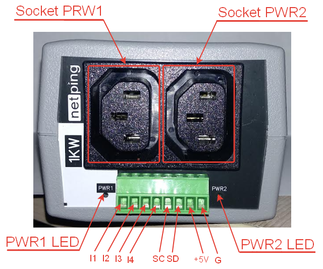
Back View
| Element | Description |
|---|---|
| Socket PWR1 and Socket PWR2 | Output sockets for remote control (switching on/off, rebooting) the load. Switched load power is up to 1,5 kW (in total, for both channels with a random distribution between the channels). |
PWR1 LED and PWR2 LED | Socket LEDs. Glowing when switched on (there is the voltage at the output), not glowing when switched off (there is no voltage at the output). |
| I1-I4 | IO lines for connecting external sensors of "dry contact" and controlling running devices. Specification of the line in the "input" mode:
Line specification in the "output" mode:
|
| SC/SD | A bus for connecting the i2C sensors |
| +5B | Power voltage for external sensors or running devices. An acceptable range is 5..5,3V and output current is 250mA |
| G | Common |

